Wednesday 31 December 2014

2015

Dear readers of this blog,

Best wishes for 2015 with lots of radiofun


     Masterpiece of engineering; "Spijkenniserbrug" near Pernis over the "Oude Maas"


Pernis Railways


                                        Wisent near "Amsterdamse Bos"

                                           Haarlem

                                       Haarlem, Spaarne, April 2015

                                     Haarlem, Spaarne II

Monday 29 December 2014

Circuit diagrams of 13 cm ATV transmitter

In order to remember the 13 cm ATV project later with the proper details I made three drawings in "Paint". I made a .bmp circuit drawing of the transmitter, baseband circuit and microphone amplifier:


ATV transmitter

Baseband circuitry


Thursday 18 December 2014

Lissajous

I found an old photo of a physics experiment I did in highschool back in 1979.
It shows a Lissajous curve. A lightbulb on a string draws the lines of the curve on
a film in an analogue camera set to high exposure time.
Black/white only since I developped the picture in the old-fashioned way (with patterson development tank and fluids; no smartphones with Megpixels available at that time).


Saturday 13 December 2014

Stereo microphone


During last visit of the PI4RAZ club meeting there was some used equipment for sale.
I found a nice Philips N8402 dynamic stereo microphone.
I hope to use this mike for the ATV video transmitter under construction.

More tech info about this microphone (designed around 1970):

http://www.radiomuseum.org/r/philips_n8402n_840.html

                                Stereo microphone Philips N8402

Tuesday 18 November 2014

eQSL from Sochi

A recent digimode 28 MHz QSO with RV6AVG from Sochi was confirmed today:


Wednesday 12 November 2014

KISS Baseband circuit

I was surprised to find a design from Pieter, PE1ODJ, in my mailbox. It shows a simple design for a proposed baseband circuit.
The circuit combines 2 audio carrier waves (at 7.02 and 7.2 MHz) with a video signal.
The audio carrier waves are combined in a one transistor common base circuit with an amplification factor 2. Due to the low resistance input at the emitter intermodulation between the 7 MHz audio signals is prevented.
The video signal is fed through a transformer-bridge circuit. The transformer uses a T50-2 Amidon core. This circuit garantees a good seperation between video and audio signals.

November 23 this circuit was succesfully activated in combination with my 13 cm ATV QRP transmitter (with one 7 MHz oscillator). Audio can be improved by a circuit that biases the high audio frequencies. Hope to add the second 7 MHz oscillator on short notice.

Dankjewel Pieter.


                                                ATV transmitter under construction

Tuesday 11 November 2014

Walkman

After inserting 2 new penlight AA-batteries in my 30 year old walkman, the device came to live. And the sound quality was not even bad. Amazing that music cassettes with this age still keep their magnetism !


http://nl.wikipedia.org/wiki/Walkman

Thursday 30 October 2014

Chromecast

This device from Google brings internet video to your TV; it gives some brains to a dumb TV with an HDMI port. 
For  35 euro  I purchased this gadget ("Mediamarkt") and I am quite happy with it. I can send wireless internet to my Samsung TV now. Most of the times I use it to watch YouTube or websites via the Google’s Chrome browser (using the tab casting feature). 
You must have access to a wifi network. It is not possible to connect the Chromecast dongle to a LAN-connector.

It is funny that you can cast video via your smartphone as well when you have the Chromecast app installed. The development of lots of apps that can work with Chromecast is on going.
I think it is a smart, inexpensive and usefull gadget.


Chromecast dongle

                         YouTube in action on my TV showing a homemade BITX20A

Friday 24 October 2014

13 cm radiolink budget analysis

I discovered that the video signals from my 2 Watt 13 cm transmitter reach the PI6ZTM repeater, normally producing an acceptable picture.

A link budget analysis can be made for this signal path:

Transmitter side (36.9 dB)

Transmit power: + 33 dBm
Note: Pdbm = 10.log (1000.2W)= 33.01

Cable losses: -4.1 dB
Note: consists of
- RG/6U; 34 dB/100m => 3.4 dB (for 10 m)
- Mismatch due to use of 75 ohm coaxcable: swr = 75 ohm/50 ohm = 1.5 => additional losses: 0.2 dB
(ref. www.deman.in.nl/Antennas/Voedingslijn/VERLIEZEN%20BIJ.pdf)
- Connectorlosses 0.5 dB

Antenna Gain: 8 dBi
Note: biquad homemade

Receiver at PI6ZTM repeater site (87 dB)

Antenna Gain: 10 dBi
Note: estimation waveguide slotted antenna

Cable/connector losses: - 3 dB
Note: rough estimation

Sensitivity threshold receiver: -80 dBm 
Note: rough estimation


Propagation (-116.1 dB)

Propagation loss: -116.1 dB
Note: Friis formula: Lp=92.45 + 20.log(F) + 20.log(D)
F in GHz and D in km makes:
Lp=92.45 + 20.log2.4 + 20.log6.3 = -116.1

Now we can calculate the link margin:

(Transmitter) + (Receiver) - (Propagation) = 36.9 + 87 - 116.1 = 7.8 dB

This value is within the range of 6...10 dB which is required to obtain a good radio link ('rule of thumb').

Note: The receiver sensitivity, cable/connector losses and antenna gain at the repeater site are estimates. The receiver (in fact converter) is mounted a few meters from the antenna hence cable losses are not that high.

http://www.pi6ztm.nl/index.php/gezien-op-pi6ztm


Sunday 19 October 2014

13 cm experiment

It turned out that you do not need to make a complicated circuitboard with stripline technology or other hi-fancy stuff to generate a 13 cm RF signal.

Yesterday I was able to transmit a video signal in the 13 cm band (on 2335 and 2365 MHz) to the video repeater PI6ZTM with a modest setup.


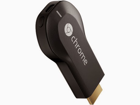
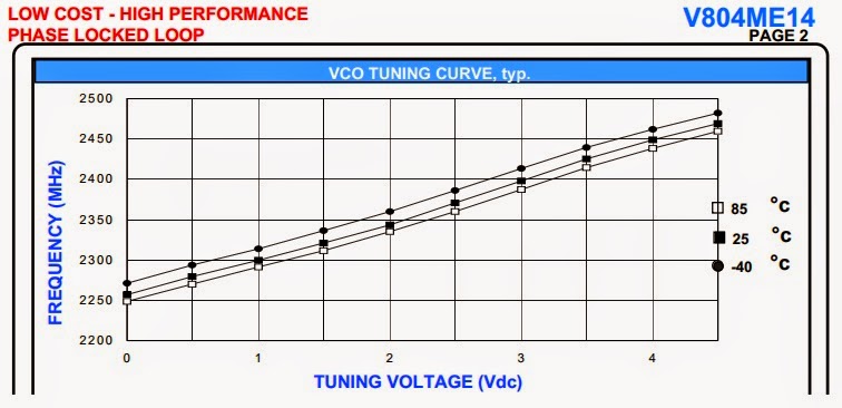
I made a small videotransmitter which provides about 10 mW (I guess) using a Z-Comm VCO  V804ME14.


Z-comm PLL VCO V804ME14


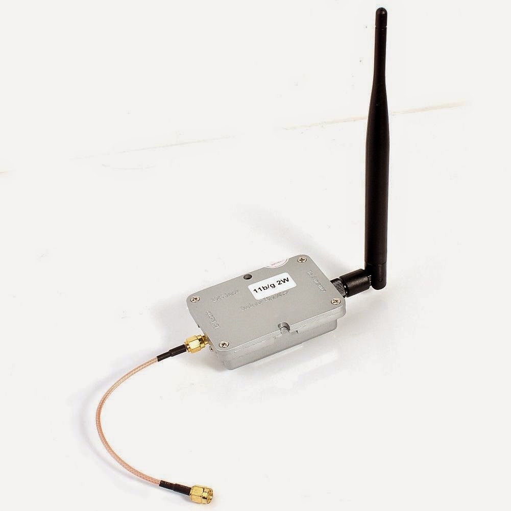
Th V804ME14 is followed by an MSA-0886 for some gain. Of course 10 mW is not sufficient to bridge a couple of kilometers. A PA was required. These days it is not really smart anymore to homebrew an RF amplifier at this high frequency yourself. A variety of WiFi boosters supplying 2..5 Watts are available. I bought a 2 Watt "Wifi 802.11b/g Wireless Broadband Amplifier Router 2.4Ghz Power Signal Booster" for $25 on ebay. 

                                          2 Watt WiFi broadband amplifier for 2.4 GHz

I received some comments from experienced ATV ham amateurs (PE1ODJ and PE1DWA); they informed me that the picture shown on the repeater channel was not too bad. After I directed my small biquad antenna better to PI6ZTM sometimes the picture was almost free of noise and glitches (but not always :-)  ).


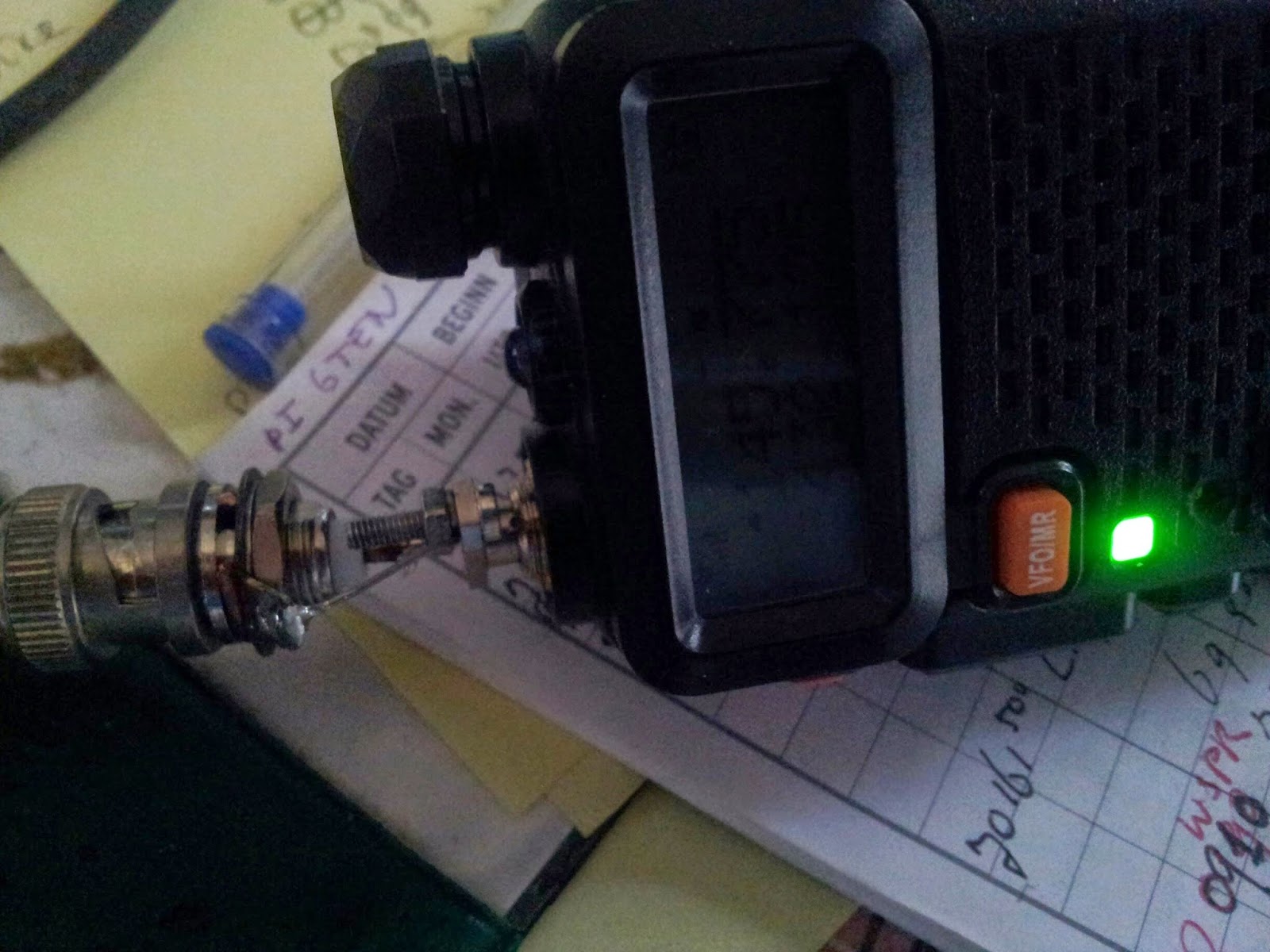
                                      Simple videotransmitter setup for 13 cm 
(..if you cannot fix it with ducttape you are not using enough ducttape... :-) )


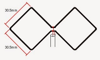
                             Dimensions biquad antenna for 13 cm

Friday 10 October 2014

Programming cable for UV-5R

For programming the UV-5R in channel mode you better use a PC. The Baofeng UV-5R handheld transceiver uses an RS232 interface to communicate with a PC. The circuit of the programming cable presented here contains a 3V3 level converter. A 2.5 mm loudspeaker plug and a 3.5 mm microphone plug connect the radio with the PC. In the software select the proper COM port.

The software to program the variables (frequency, shift, channel name...) can be found here:


Saturday 4 October 2014

External antenna for UV-5R

It is easy to extend the transmit/receive range of a handheld transceiver. Simply connect a better, external antenna.
I made a simple SMB-BNC joint to connect an external antenna to my UV-5R.


With a 2m  HB9CV antenna it is quite easy to reach the repeater stations.
The repeater PI3UTR in IJsselstein came into range for me now on 145.575 MHz (shift 0.6 MHz, 77 Hz TX subtone) and it is rather easy to make FM QSOs.

The TX antenna of the repeater is located at an altitude of 220m and the receive antenna even higher (300 m). This repeater covers at least half of The Netherlands.

http://www.pi3utr.nl/

HB9CV for 145 MHz


                                      Gerbrandytoren Lopik, with PI3UTR repeater

Note: On the PI2NOS repeater (430.125 MHz) I was informed by Rob, PA3CNT that I should select 'WIDEBAND' in menu item 5 (W/N) of the porto to enlarge the modulationdepth of the transmitted signal. So I did, and modulation quality has certainly improved.

Tuesday 23 September 2014

First voice contact with Lebanon

Last weekend, on 28 MHz, I made a first (Es) QSO with Lebanon. Walid, OD5ZZ gave a 599 to my call in USB. Via eQSL I received the confirmation of the contact yesterday.


Tripoli, Lebanon

Monday 22 September 2014

UV-5R dual band handheld

SInce last week, I am the owner of a UV-5R dual band transceiver.
On e-bay you find plenty of offers for this type of radio. I bought the rig for 25 euro's.
Amazing what you get these days for this price:

The Baofeng UV-5R is a compact handheld transceiver providing 4 Watts in the frequency range of 136-174 MHz and 400-480 MHz. 
It is a compact transceiver  that includes a special VHF receive band from 65 - 108 MHz which includes the regular FM broadcast band. 
Dual watch and dual reception is supported. You get up to 128 memory locations. 
Other features include:  selectable wide/narrow, battery save function, VOX, DCS/CTCSS encode, key lock and built in flashlight. 
Selectable frequency steps include:  2.5, 5, 6.25, 10, 12.5 and 25 kHz. 
RF power selectable at 4 or 1 Watts. 


This radio comes with ANT5 SMA-J flexible antenna, BL-5 Li-ion battery (7.4V 1800 mAh), belt clip, wrist strap, AC adapter (8.4V 600 mA) and drop-in charging tray. 
This radio has been provided with a male SMA antenna jack. 

I found the control of the radio rather straight forward (menu driven) though programming the memory channels was not that easy.
This weekend I have been able to contact some nearby repeaters (Zoetermeer 145.750 MHz, Rotterdam 430.300 MHz, Den Haag 430.350 MHz).
Allthough I enlarged the microphone opening in the housing, I received some complaints that the audio modulation on 70 cm is too weak. 

Saturday 6 September 2014

Not much radio

During the holiday period, we are in Greece near the village of Parga. I decided not to take radio gear with me. I find myself now and then looking into the skies searching for satellite dishes, yagis and long wires :-) All the best from SV country (Epiros).


Parga, Valtos Beach


Meteora, September 8


Arta, September 9


Dodonis, September 7


Friday 29 August 2014

On the cover of a magazine

Funny. The article about the "Hollands Glorie" receiver was published in the "QRP Benelux" newsletter. Club info: http://www.beneluxqrpclub.nl/
For the first time I am on the cover of a magazine :-)


See also my blog entries of May 18, May 29 and July 4 this year.


I hope the article will inspire some readers to heat up their soldering iron.

https://www.youtube.com/watch?v=fJu6Up9w2Hc

Tuesday 26 August 2014

Canadian industrial heritage

A nice surprise this morning in the office. A collegue showed some beautiful pictures of Canadian industrial heritage. Allthough off-topic, I would like to share these pictures which Guy took during his recent visit to the Heritage Park in Calgary, Alberta (Canada). Amongst others, they show steam locomotive 0-6-0, CPR2023 of the American Locomotive Company, Shop No 70388, manufactured in Sep. 1942.


More info about the park: https://www.heritagepark.ca


This week I came accross railway station "Geldermalsen" which is being reconstructed. 

Saturday 16 August 2014

eQSL from Senegal

eQSL sometimes really surprises me. This week I got this eQSL from Peter, 6W2SC.
The card confirms a 20m RTTY QSO back in 2006 :-)
QSO's with Africa are very rare anyway because of the simple fact that people can not afford money spent on a hobby. Therefore the number of radio amateurs is not high and I treasure each QSO made with Africa.


Casamance, Senegal:


Saturday 9 August 2014

23 cm ATV transmitter works

This week I did some succesful experiments with the 23 cm FM ATV transmitter with ALPS VCO. The transmitter provides about 30 mW to an 23 cm PA which delivers 1...2 Watts at 1.2 GHz. One of the tranmissions shows my testpicture at the PI6ZTM repeater:


I did not include PLL circuitry in the design. The circuit is straight forward:


The video branch contains: CCIR-filter, VCO ALPS 1679C and MMIC MSA-0886.

August 12, I was able to test the audio part (7.02 / 7.2 MHz oscillator). It worked, but there was some 50/100 Hz hum. Also I found that results were better when the 7 MHz signal was injected just after the 50 k potmeter.

The VCO can be tuned from 1100...1350 MHz.

At this moment, the experimental circuit is soldered on unetched PCB.


                                             23 cm ATV transmitter

The ATV transmitter is connected to the Power Amplifier (design PA0VRE):

                                                    2 Watt PA with BFQ68 and BFQ136

The PA delivers its output signal to a homemade biquad antenna, connected with about 8 meters RG6U coaxial cable (75 ohms).

More testpatterns:


To my surprise the transmitter is very frequency stable. No PLL circuit required !

Saturday 2 August 2014

Handycam

On a fleemarket I found a nice, old camrecorder to provide me with moving images for ATV experiments.
It is a Sony Handycam from around 1990. It is a camera/recorder using Video 8 tapes. At the time a revolutionary device because of its palm sized dimensions and good picture quality.


The Handycam delivers a composite video signal (yellow cinch plug) which I can feed directly into the ATV transmitter (with the ALPS VCO)

Sony still uses the brandname "Handycam" for its current digital cameras:

http://en.wikipedia.org/wiki/Sony_Handycam_NEX-VG10

All about the Sony Handycam:

http://en.wikipedia.org/wiki/Handycam

Recording made with Handycam transmitted on 1.2 GHz